3D-printed hand-wired Macro pad with Raspberry Pi Pico, KMK & CircuitPython
Laatst bijwerkt op vrijdag 16 september 2022.
It’s been a while since I’ve written a post, and a lot has happened in that time. Most importantly, after 3 years I left Sogeti, to continue as a Sr. Frontend Developer at Total Design. I’ve only just started, so I can’t say much about it yet, maybe in a future post. With my current schedule, that should probably be around 2023. ;-)

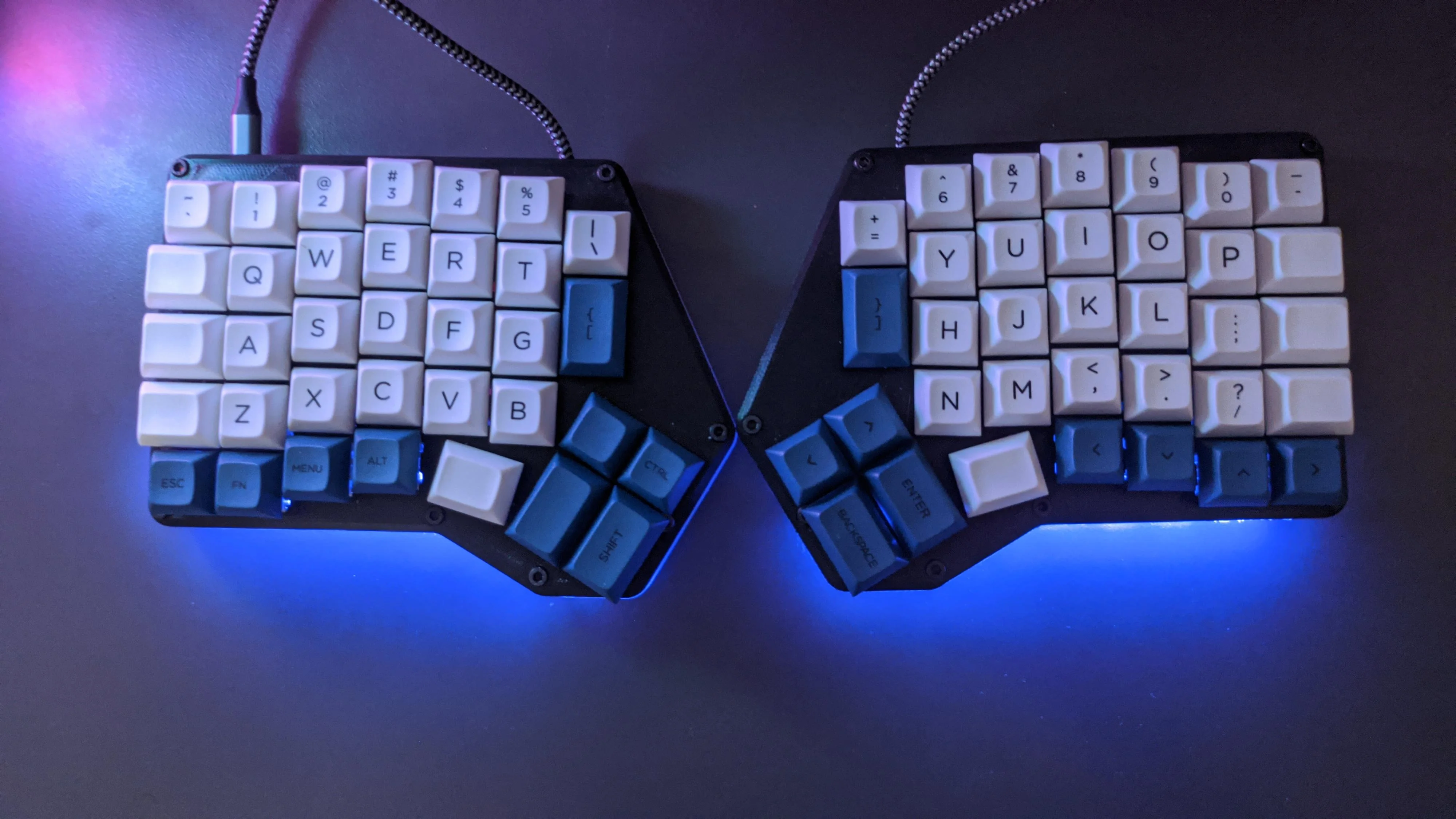
In this post I want to explain how I created my new macro pad, but first maybe an explanation of why I created it. My ultimate goal is to build a split keyboard, specifically the Redox v1.
The thing is that making a whole keyboard right away is brave. The last time I successfully soldered was sometime in my youth when I took an electro-mechanics course. There’s a good chance I’m taking too much on my fork with a full keyboard. A macro pad is a lot cheaper, less work, and with how I designed it, I can reuse a lot of the parts if it should fail. I have so much confidence in myself…
The Redox, like most split keyboards, has no number pad. When I create 3d designs in Fusion 360, I often enter numbers via the number pad because it works faster for me, so it’s essential for me, but not essential enough to have it on my desk all the time.
If you want to make one too, you’ll need the following.
Bill of Materials
- 24x Cherry MX switches (I got the Blacks purely because my local electronics store had them in stock) - €1.45 x 24 = €34.80
- 24x Rectifier Diodes (Doesn’t matter which one, I used the 1N4004) - €5.00 for 100
- Raspberry Pi Pico - €8.95 (or €44.95 for 10)
- Mounting cord - 0.4mm² / 21AWG - €2.60 for 5m (I took red and black for distinction)
- 4x M3 Threaded Inserts - €12.80 for 100, €28.90 for set of 200 M3, M4 and M5’s in total
- 4x M3 screws - €3.29 for a set of 30 including nuts
- 4x Protective pads - €2,19 for 9
- Soldering tin - €13.45 for 100g
- Printed models
Tools
- 3D printer
- Soldering iron
- Cable stripper
- Multimeter (optional if you are a solder god who never makes a mistake. So get 2.)
I have chosen to print my key caps, not only to cut costs, but also so that I can print new caps at any time if I want to switch functionality. Because I already had the threaded inserts, the price I had to pay for the materials is €67.88. This is more than 3x as expensive as the cheapest number pads I could find at Coolblue and Mediamarkt, but of course you can’t program them yourself.
The biggest expense was in the switches, and I admit I could have gotten them a lot cheaper. The reason I didn’t put them online, which would have saved me almost half, is that I’d be left with a delivery time of several days. This would mean that I couldn’t work on it this weekend, but couldn’t start until next weekend. I knew I had time this weekend, but who knows what’s in store for next weekend. And instead of building it in a weekend, it becomes one of those projects that you “someday” finish “when you have time”. If that means that I have to pay 15 euros more for the switches, I find that difficult to see as a negative.
Step 1: Assembly
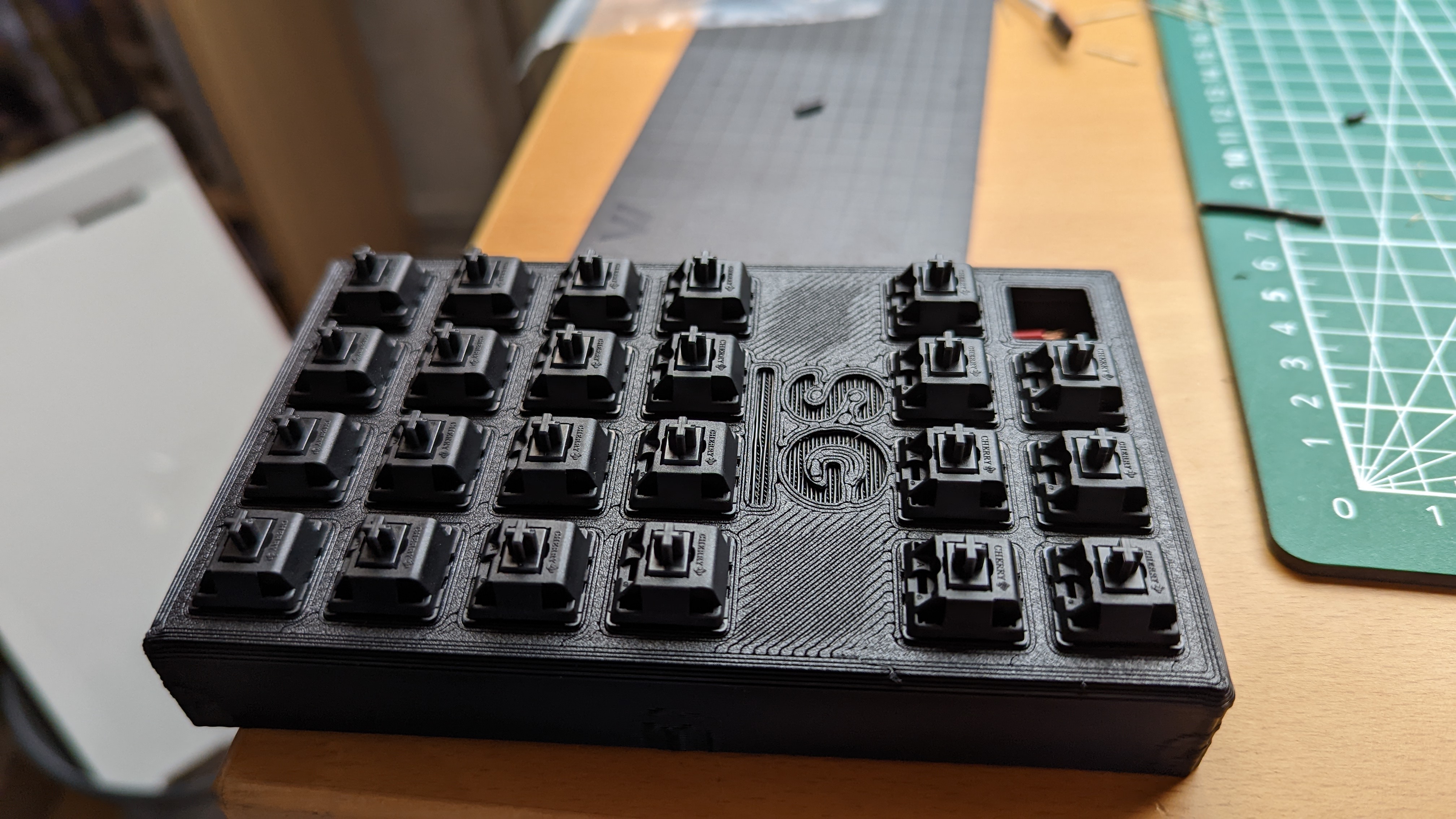
If you want to make this macro pad in a weekend, the first print you need to turn on is the top plate. You can print the other prints later, but without the top plate you can’t start soldering. You can get the whole project workable before you print the keycaps and the bottom. In terms of print settings, I printed the case with a 0.6mm nozzle with 0.45mm layer heights, to have it ready as soon as possible. The keycaps are done with a 0.4mm nozzle on 0.16mm layers.
When the printer is ready, you can start pressing the buttons in the print. Make sure you do them all the same. With Cherry MX switches you can make sure that the logo is at the top.
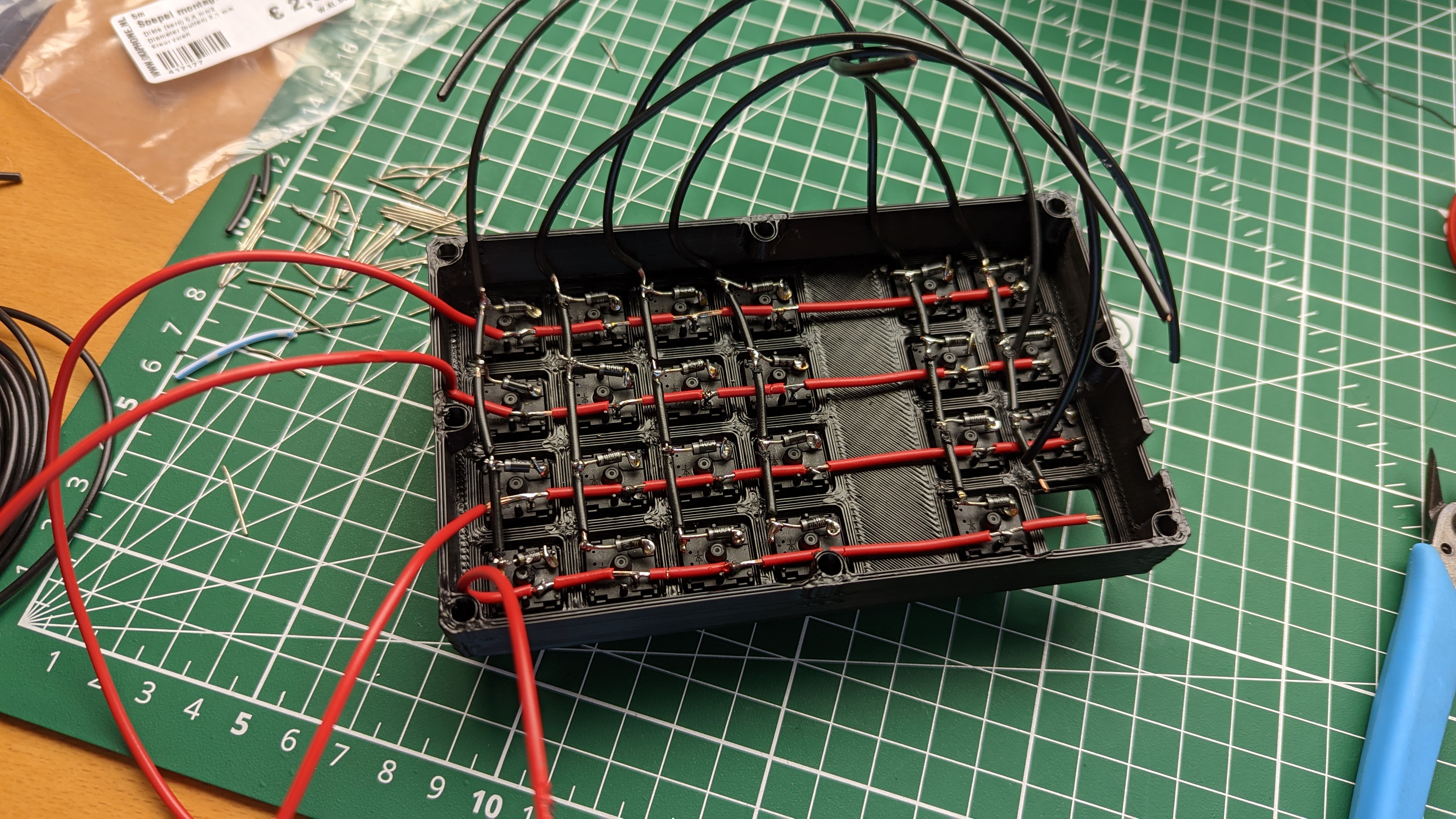
Once you’ve done this, you can begin the most time-consuming work of the project. Cut the insulation of the cables so that there is always a small opening to solder the cable to the switch or the diode. After several failed attempts I found a way that worked easily for me. You start by stripping off a large portion of the insulation first. I did about 4 cm for the columns, about 2 for the rows. It’s easier to cut wire later if you’ve left too much open than to have to free up extra space later. Then you measure approximately the distance where insulation should be between the 1st and 2nd switch and strip it. you then slide the insulation forward, leaving enough room to solder the end to the first switch. You repeat this for the 2nd and 3rd switch, until you finally have small pieces free to solder all switches to the first cable. In this post I’m not going to talk about how to solder, because I’m also a huge beginner at it.

Once you have the first cable, you can repeat the process for the rest of the columns. For the rows you can also choose to solder the diodes directly together, but I chose to run a 2nd cable between them, so that there is more insulation on the cables. Pay close attention to the polarity of your diodes. The 1N4004’s have a gray band to indicate where the current flows. It doesn’t matter which side you choose, as long as you know what’s what, and you pick the same side with every diode. If you flip them over, it won’t work.
As a final soldering job it is now time to attach everything to the Pico. Important here is mainly that you know which rows and columns are attached to which GPIO pins. I packed GP16, GP17, GP18 and GP 19 for the columns, and GP14 to GP8 for the rows. I read on the internet that there are problems with GP15. I didn’t test this, but that’s why I didn’t take it.
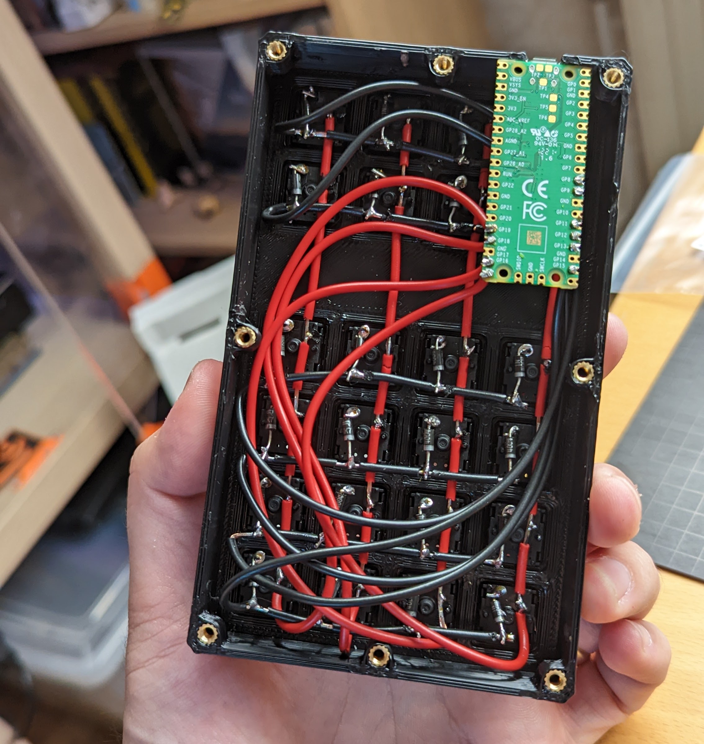
And that’s it! Now we can test if it works.
Step 2: KMK
Before we can start pushing buttons, we need to install CircuitPython and KMK. For the installation I link to this video by Craig Manning which explains step by step how to put KMK on a Pi Pico.
One thing the video doesn’t show great is the full code.
Main.py
print("Starting")

import board

from kmk.kmk_keyboard import KMKKeyboard
from kmk.keys import KC
from kmk.scanners import DiodeOrientation
from kmk.extensions.media_keys import MediaKeys
from kmk.modules.layers import Layers
from kmk.handlers.sequences import send_string

keyboard = KMKKeyboard()
keyboard.extensions.append(MediaKeys())
keyboard.modules.append(Layers())

keyboard.row_pins = (board.GP8, board.GP9, board.GP12, board.GP13, board.GP14, board.GP11)
keyboard.col_pins = (board.GP16, board.GP17, board.GP18, board.GP19)
keyboard.diode_orientation = DiodeOrientation.COL2ROW # From Column to Rows, if you switch the polarity, it's ROW2COL

# Cleaner key names
_______ = KC.TRNS   # Transparent   -> Clicks through to previous layer
XXXXXXX = KC.NO     # No Action     -> Stops click through

FnKey = KC.MO(1)

VIDEO = send_string("https://www.youtube.com/watch?v=dQw4w9WgXcQ") # Very important video

keyboard.keymap = [
    # Base Layer
    [
        KC.AUDIO_MUTE,  KC.LCTL(KC.V),	KC.BRIU,    KC.AUDIO_VOL_UP,\

        FnKey,          KC.LCTL(KC.C),	KC.BRID,    KC.AUDIO_VOL_DOWN,\


        KC.N7,		KC.N8,		KC.N9,	    KC.BSPACE,\

        KC.N4,		KC.N5,		KC.N6,	    KC.ASTERISK,\

        KC.N1,		KC.N2,		KC.N3,	    KC.PLUS,\

        KC.N0,		KC.DOT,		KC.EQUAL,   KC.ENTER,\

     ],

    # Fn Layer
    [
        XXXXXXX,	VIDEO,	    	XXXXXXX,    XXXXXXX, \

        _______,	XXXXXXX,	XXXXXXX,    XXXXXXX,\


        _______,	_______,	_______,    KC.DELETE,\

        _______,	_______,	_______,    KC.SLASH,\

        _______,	_______,	_______,    KC.MINUS,\

        _______,	KC.COMMA,	_______,    _______,\

     ],
]

if __name__ == '__main__':
    keyboard.go()
Boot.py
import supervisor
import board
import digitalio
import storage
import usb_cdc
import usb_hid

# This is from the base kmk boot.py
supervisor.set_next_stack_limit(4096 + 4096)

# If this key is held during boot, don't run the code which hides the storage and disables serial
# To use another key just count its row and column and use those pins
# You can also use any other pins not already used in the matrix and make a button just for accesing your storage
#
# GP16 <-> GP9 is our Fn key. if yours maps to different ports, update it here. Else you won't be able to update
# your firmware anylonger.
col = digitalio.DigitalInOut(board.GP16)
row = digitalio.DigitalInOut(board.GP9)

# TODO: If your diode orientation is ROW2COL, then make row the output and col the input
col.switch_to_output(value=True)
row.switch_to_input(pull=digitalio.Pull.DOWN)

if not row.value:
    storage.disable_usb_drive()
    # Equivalent to usb_cdc.enable(console=False, data=False)
    usb_cdc.disable()
    usb_hid.enable(boot_device=1)

row.deinit()
col.deinit()
If you followed these steps, your custom macro pad should now work!
Step 3: Finishing touches
You should now have a working macro pad. If none of the keys work, check that your diodes are in the right direction, that your code is correct, and that you have set the correct GPIO pins. You can also check with a multimeter whether the cables are connected. If not, you know you made a mistake somewhere while soldering, if so, it’s probably the code.
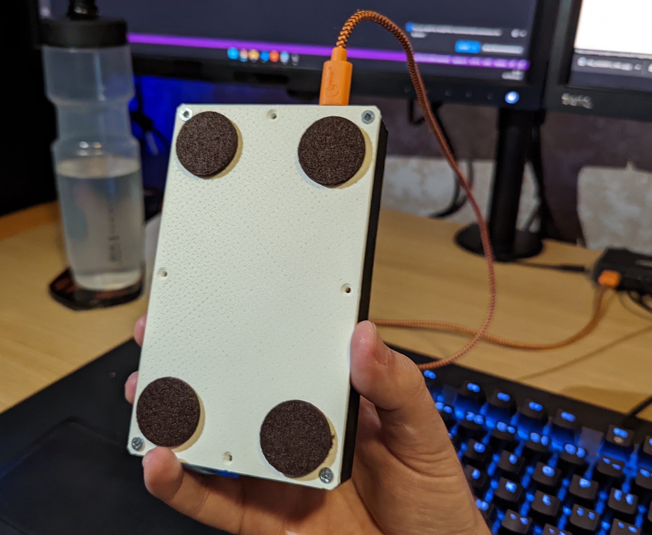
I hope you haven’t forgotten to turn on those last prints in the meantime? Yes? Then come back after a few hours… Ah, you’re back? Beautiful. Now we just need to attach the bottom. In the models I left room for 8 threaded inserts, but you only need the 4 corners. You can never have too many places for screws, because if you don’t need them, just don’t screw them in like we did here. Finally, I put some felt stickers on it, so that the keypad slides less around on the desk.
If you make one, send me a picture! The best way to do that is to upload it as “Make” to Printables, or send me a message via LinkedIn. Have fun building!